segunda-feira, 28 de abril de 2014

Graph Mappers and Waffling

Assignment Concept: For this assignment, I wanted to design a model that would show the contrast between the complex curvature of the general form and the bi-dimensionality of each piece that constitute it when using a waffling technique. Below I detail each part of the script and creative process.

Triangular shapes: To get the a smooth curve that would contrast with the box that I wanted to use as support, I decided to use the Graph Mapper, a component that I hadn't used before. After seen a couple tutorials, I came up with the script below, that defines triangular shapes based on a curve defined using two Graph Mappers.
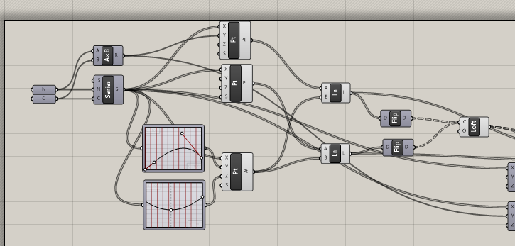
Script for the triangular surfaces
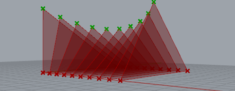
Triangular surfaces defines by 3 point sets, one of them using Graph Mappers

Cutting the surfaces: The model above seemed too simple for the assingment, so I decided to cut the surfaces in order to get varying cuts in the support when waffling.The void was also created using Graph Mappers.
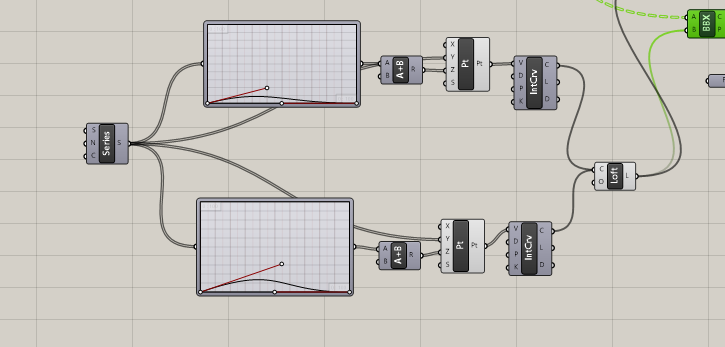
Script for the trimming surface
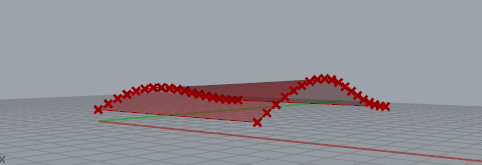
Void that will cut the triangles

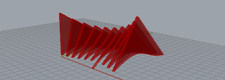
Triangular surfaces trimmed and lofted
Support: I wanted to make the support element as surfaces that would give the feel of a box, working as a canvas for the more complex shape of the triangular surfaces. For that, I used a 2-point box, moved using a series and then cut. Note that I had to create another void surface in order to make the gaps open in a way that facilitates assembly and gives a feel of order and regularity for the model. I also decided to only make the dents in the structure in order to keep the bottom of the triangles intact, making the design rely on the tight fit of the cardboard.
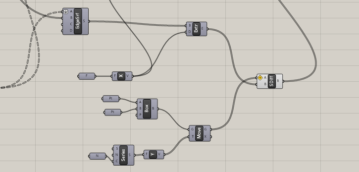
Script for the structural element
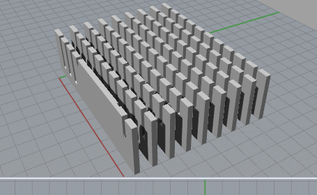
Support elements

Final Design
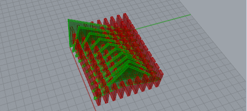
Laser-cutting patterns: Putting the shapes in planes in order to laser cut them was fairly straightforward, with the exception of the supporting elements. Since those where created based in Breps rather than from surfaces, I had to deconstruct them and figure out how to use only the faces I wanted. I managed to do that by removing the items with small areas and them the repeated ones.

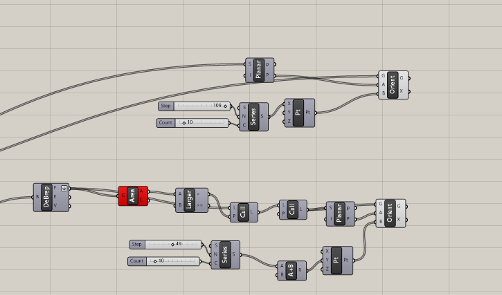
Script for defining the cutting surfaces
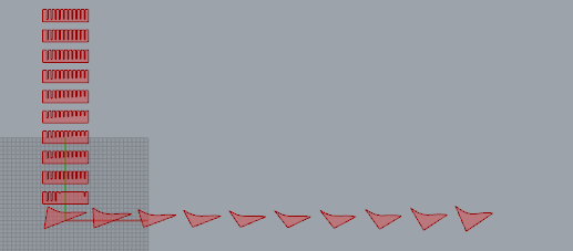
Cutting surfaces

terça-feira, 1 de abril de 2014

Sloped surface using attractor points

Sine Wave: The chosen method to generate the model was to use a sine curve as the basis of it, not just as the attractor points. The dimensions of the model are defined by the wavelength and amplitude of the sine, as well as the number of wavelengths used. as the script bellow shows, first the sine wave was created (allowing it to be adapted trough multiplication modifiers) and then, using the coordinates of its points, a field of points is generated.

Script for the sine wave and field of points
Sine wave and field of points


Attractor and lines: Afterwards, the sine points were used as attractors, generating a three-dimensional field of points (which generated extra information, making the use of a Range modifier necessary). Then, each point was connected to its correspondent* in the XY plane, generating the lines which will form the surface.
*Represented here as a new element to facilitate the reading

Script for the field of points and the lines

Field of points generating lines
Surfaces and final model: To get to the final result, two lofts were used: one connecting lines in the X axis and one connecting the lines in the Y axis. This would ensure the model is structurally sound. The final model is the result of these surfaces extruded in their respective axis'. The script was thoroughly tested in order to check if the change of parameters would break the model, but after some small changes, it proves to be completely adaptable.
Script generating the surfaces and the model

Final model
Model using different parameters

segunda-feira, 17 de março de 2014

Script for a G in Grasshopper

The G has a simple shape, which can be drawn fairly easily in Grasshopper and it could be used in various different ways as a three-dimensional shape. In my particular script, I chose to prioritize adaptability and flexibility over the complexity of the model, because for me that's where the strength of parametric and generational modelling lies. Each part of the modelling process is detailed below and the script can be download in the bottom of the page:

Model of the complete script


Arc: The first element defined was the main arc of the G. This was achieved creating an arc component with the arc angle and rotation angle parametrized, allowing for quick adjusting later on. The rest of the surface was created using this component and an offset component with an adjustable distance.

Script for the main arc

Descender and crossbar/Support: Doing the support script after the arc was important to ensure the adaptability of the script. Using the x coordinate of the outer arc, the position of the beginning of the support could be defined. Both the width and the length of the pieces are parametrized and linked to slider bars, allowing for adjustments and experimentation. It was also important to use information from the arc to define the empty space where it would fit.

Part of the script for the support structure


Preparing for printing: To use the defined faces for printing it was necessary to put then in a single plane. To achieve that, the example script showed in the blog of the discipline was adapted, in order to work with the model. The main challenge was to make it work with all the different changeable parameters in the model, but using the data from the other components, this problem was solved, making any change to the main model automatically adjusting the planning faces for printing.

Script used to make the support planar